
How to reduce the operation cost of the water distribution system?
For years, engineers have been pursuing their goals in water distribution systems, focusing on ensuring pressure and flow control, as well as reducing operational costs.
Firstly, the old systems, such as Swirl flaps and three-way valves, are examples of methods that have been used to regulate pressure or flow in booster pump applications, thereby moving the pump operating point along its characteristic curve. In this old system, there is no chance to minimize energy consumption.
On the other hand, the old system’s operation applied high pressure to the mechanical parts, which caused more mechanical faults that reflected on the operation cost.
And after a while, the engineers found a way to achieve their goals of pressure or flow control and reducing operation costs by controlling the pump speed.
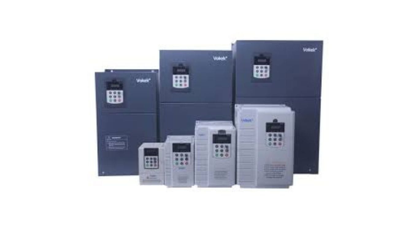
This method will mainly depend on the Variable Frequency Drive (VFD)
VFD will be used to provide your water distribution network with the required pressure and flow as per the actual demand, which is achieved by controlling the pump speed.
What is the Multi Motor Follower (MMF) function in Master-Slave Variable Frequency Drives (VFDs)?
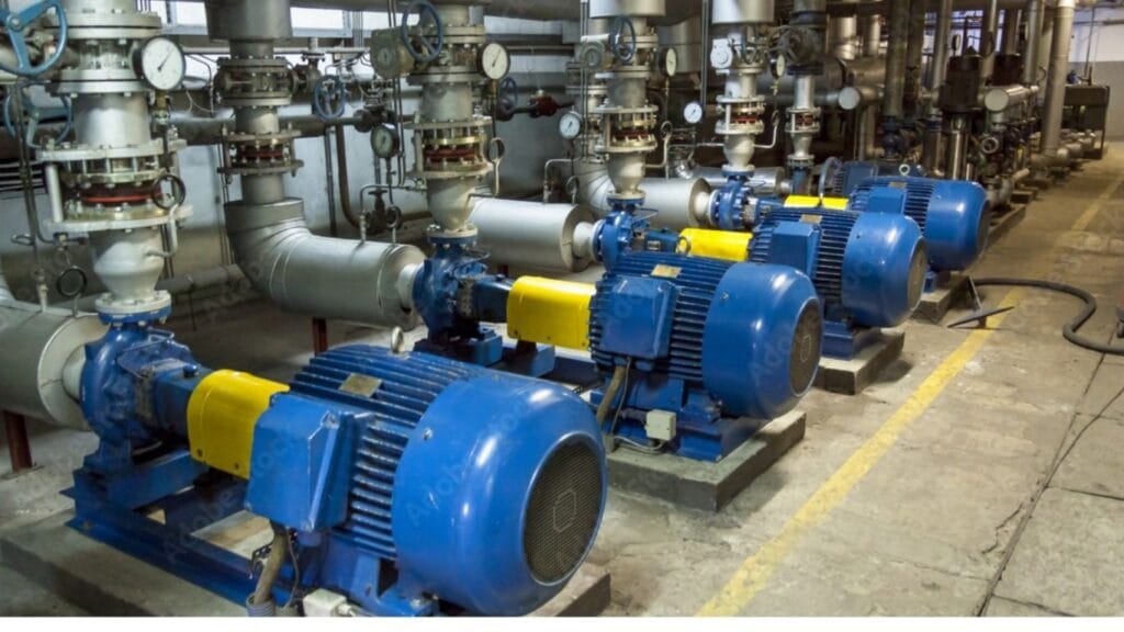
The primary purpose of this method is to maintain a constant pressure in the water distribution network. The MMF system can be used when the water distribution system is fed by more than one equal-sized pump. An individual VFD unit will control each pump.
All units will communicate with each other to coordinate system operation.
Some VFDs are equipped with a Master-Slave option, allowing up to 8 units to be connected in one system via RS-485 communication. One feedback signal from the pressure transmitter will be sufficient to control the whole system.
Once the system receives the start signal, one of the drives will be designated as the leader (master), and the other drives will operate as slaves (followers).
The PID function will be active to calculate the error between the set value (PID reference) and the feedback value.
Based on the difference between the set value and the actual value of pressure in the water distribution network, the MMF system will provide instructions to all units to adjust the pump speed that maintains system pressure using the PID Function.
The MMF system also offers the option to calculate the operation time for each pump. Depending on this, Master VF, the suitable pump will be energized using the Equal Aging function, which will increase the pump’s lifetime.
In the following example, we will explain the MMF System:
Let’s say there is a commercial building equipped with an MMF system to manage its water distribution network.. When network demand increases, the pressure in the network decreases. Due to this, Master VFD will increase the pump feed by increasing the speed of the main working pump.
After the real operating speed reaches a certain level, the adjustable delay time elapses, and the pressure does not get the set value.
Then, the Master VFD will energize another VFD and decrease the speed of the main pump. After that, the Master VFD will monitor the speed of the energized VFDs to ensure the pump speed meets the target pressure and maintains it at a constant level.
When system demand decreases, the pressure in the water network increases. Master VFD will reduce the water feed by adjusting the speed of the operated VFD units, then stop it if the unit reaches a specific speed. The exact sequence will be applied to the next unit till the system pressure matches the pressure set point.
In conclusion, the primary benefits of utilizing the MMF System are:
- Energy savings achieved through pump speed control (20% / 50%) based on Affinity laws.
- Multi-Pump Multi-Drive duplicates energy saving.
- Reduce maintenance by equalizing run time for all pumps.
- In old and weak pipe systems where significant pressure surges can lead to leakage, the high performance of the MMF system can be a real benefit.
- In constant-pressure water systems, pumps can be operated in the most energy-efficient way by using master-slave VFD operation.
- In systems with significant variances in flow, the fast-reacting MMF system will safely and fast maintain a constant pressure.